


U10W Replaces Fragile 8W Fans | Turkmenistan Cooling Tower
When the cooling tower fans serving a power project in Turkmenistan began failing, the operators needed more than a like-for-like spare. Thin, fatigue-prone blades had already cracked and shed material inside a running tower. They needed a fan that would survive the duty, and they needed it fast. This case study documents what failed, how UTEK-DELE engineered the replacement around the U10W platform, and how the new fans were tested, balanced and shipped for installation.
Everything below is drawn from the project record: the failed 8W installations, the replacement specification, the workshop photographs of the new blade sets, and the balancing and inspection data that travelled with the order. The numbers are reported as they appear on the project documents, and the design discussion explains why each change was made rather than only what was changed.
If your plant is running the same generation of thin-blade fan and you are weighing repair against replacement, this record shows how a documented upgrade path is built from measured blade data instead of guesswork.
Cooling Tower Fans: Duty, Failure Modes and Why Blades Crack
A mechanical draft cooling tower is a continuous-duty machine. The fan sits in a saturated air stream, pulls air through a fill pack where water films the surfaces, and discharges warm humid air upward. That environment is far harsher than it looks from outside the tower. The blade sees:
Constant aerodynamic load — a pressure differential that never fully relaxes while the tower is in service, and that grows whenever the fill or the drift eliminator becomes restricted;
Cyclic stress — every rotation loads and unloads the blade root once, so a fan running at 300 rpm accumulates 18,000 root load cycles per hour, over 150 million cycles in a year of continuous operation;
Moisture and chemistry — carry-over from the water circuit deposits salts on the blade surface, and the deposit pattern is rarely symmetric, so balance drifts over time;
Temperature cycling — the blade warms in the plume and cools when the tower is shut down for maintenance or trips offline;
Occasional overspeed and stall — the moment the tower loses airflow, the fan can move toward its stall region and load the blade in a direction it was not designed for.
Fatigue cracking almost always starts where the section changes abruptly: the blade root, the transition into the hub pocket, or a manufacturing detail such as a sharp internal corner. Thick, uniform sections tolerate this regime because stress is spread through the material. Thin sections with abrupt transitions concentrate stress at a single fillet, and once a crack initiates it grows with every revolution until the blade releases material into the tower.
The photographs below show what that progression looks like in practice. The failed units belong to the generation of fans the plant was running before the upgrade; they are included here because the failure pattern dictated the engineering response that followed.
Field note: Blade failures in cooling towers are rarely a single-cause event. The crack that finally releases the blade is usually the last step of a chain that starts with a thin section, continues through an unbalanced impeller, and is accelerated by deposits that change the blade's natural frequency. Fixing only the crack — by welding or patching — leaves the rest of the chain intact.
That is the reason this project did not attempt a repair programme on the existing fans. The replacement was specified against the duty, not against the drawing of the failed part.
Cooling Towers and the Fan Systems That Support Them
1. Cooling towers: the heat-rejection terminal of the plant
A cooling tower is where a power or process plant rejects the heat it cannot use. Warm water is distributed over a fill pack, air is drawn through the falling film, and a small fraction of the water evaporates and carries the heat into the atmosphere. Every degree of approach temperature the tower achieves is returned to the plant as usable capacity.
The fan is what makes that exchange happen. It sets the air quantity that crosses the fill, and therefore the heat the tower can reject at a given water flow. When the fan loses performance — or stops — the tower loses capacity immediately, and the plant must either reduce load or accept higher condenser pressure.
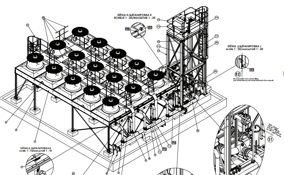
Cooling tower layout for the Turkmenistan power project, showing the fan positions served by the replacement blade sets.
2. The tower type on this project: mechanical draft, counterflow
The cooling towers in this project are mechanical draft counterflow units: air enters at the base, travels upward against the falling water, and leaves through the fan stack at the top. The design is compact for the duty it delivers, but it puts the fan in the most demanding position in the tower — saturated air, carry-over deposits and continuous operation.
That environment is what turned a blade replacement into an engineering exercise rather than a parts order, as the photographs further down this page show.
3. Why the axial fan decides reliability
An axial fan moves air parallel to its shaft, which is exactly what a tower needs: high volume at modest pressure rise. The blade carries the whole aerodynamic load as a cantilever, so blade stiffness and the quality of the root-to-hub interface determine whether the fan survives years of continuous running or fails early.
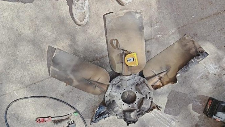
Failed 8W blades removed from the tower: fatigue cracking and material loss in the root region.
Close-up of the damaged blades and the original hub as found during the site inspection.
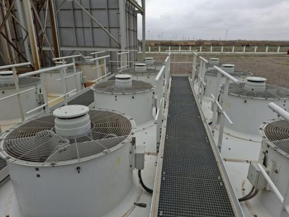
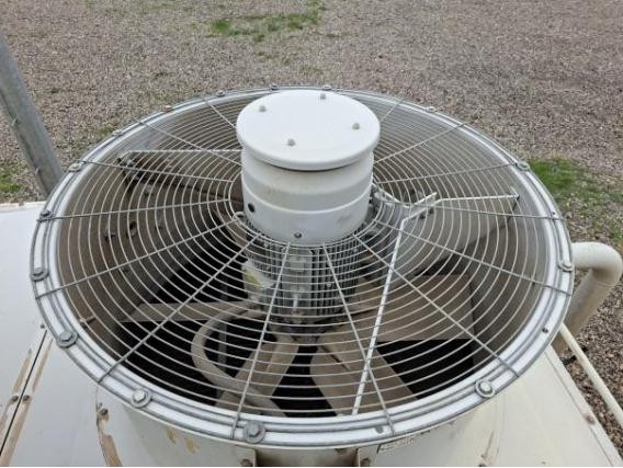
Original 8W fan installation in Turkmenistan, photographed before the U10W replacement.
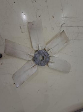
Site condition of the fan deck: carry-over deposits and continuous-duty service.
Once the failure pattern was documented, UTEK-DELE measured the existing installation and specified a replacement against the duty rather than against the failed part number — the sequence described in the next sections.
Why the 8W Design Failed in Service
The 8W is a thin-section moulded blade. In light, clean duties it performs adequately. In a cooling tower running continuously with carry-over deposits and a long cantilever from hub to tip, the same design has three structural weaknesses.
First, the section is thin relative to the bending moment. A blade is a cantilever: aerodynamic thrust is applied along its length and resisted at the root. The bending moment grows with the square of the diameter, so a modest increase in fan size raises root stress quickly. When the section is slim, the only way to carry that moment is to accept a higher stress level — and fatigue life falls sharply as stress rises.
Second, the transition from blade to hub is abrupt. Stress concentrates at geometric discontinuities. Where a thin blade meets a comparatively rigid hub pocket, the load path narrows into a small area of material. Cracks initiate there, often on the trailing side where the local section is thinnest.
Third, the assembly is sensitive to imbalance. Thin blades deflect more under load, and the deflection changes the effective angle of each blade. When deposit build-up is uneven — which is normal in a tower — the impeller becomes unbalanced, vibration rises, and the root sees an additional alternating load on top of the aerodynamic one.
The failures recorded at this project follow that pattern: material loss near the root region of thin blades, with the surrounding blade surface showing the dull, salt-marked appearance typical of long exposure inside a plume. The images that follow are the original site photographs of the damaged 8W fans and of the installation as it stood before the replacement.
Design rule of thumb: If a blade can be flexed noticeably by hand at the tip, its stiffness is being provided by the hub rather than by the blade itself. That is a warning sign in any duty where the fan cannot be inspected frequently.
Preparing, Testing and Shipping the Replacement Sets
Large fan blades are awkward cargo: long, comparatively light and easy to damage at the tip or the root. Packing therefore treated each set as an assembly rather than as a stack of loose parts, and the paperwork travelled with the blades so the site team could match every crate to its fan.
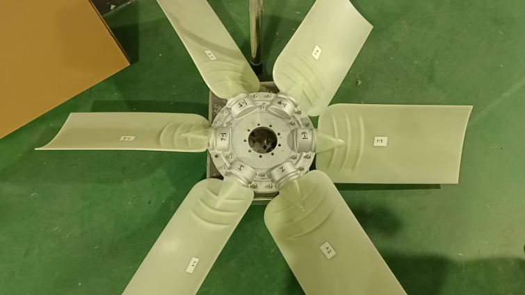
New blade set assembled and marked before packing — the angle setting is recorded per set.

Blades boxed with set identification; fasteners and hub parts packed separately for transport.
Sample test order, marked for disassembly after dynamic balancing so transport cannot disturb the setting.
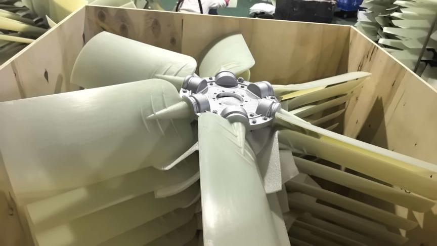
Blade sets crated for export, protected along the span and at the root face.

Loading the balanced sets for shipment to the Turkmenistan site.
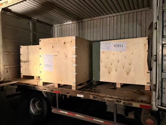
Official order documentation accompanying the shipment, including balancing and inspection records.
One detail from this project is worth repeating because it applies to every tower installation: a set that is balanced and then shipped assembled can arrive with a different balance condition than the one recorded in the workshop. Marking the set for re-assembly on site, and re-torquing to the recorded angle, is what keeps the factory record meaningful.
The Turkmenistan Power Project: Requirements and Constraints
The project is a power installation in Turkmenistan where cooling tower availability feeds directly into generation capacity. A fan failure is not a maintenance inconvenience: it reduces the heat rejection capacity of the tower, raises condenser pressure, and forces the operators to derate the unit. With that consequence in mind, the replacement brief was written around four requirements.
1. Restore the thermal duty at the existing fan ring
The new fan had to fit the existing tower opening without structural modification. That fixes the diameter and the approximate blade count; what remains open is the blade section and the angle at which each blade is set. Airflow at a given speed is a function of blade area, angle and profile, so the replacement was engineered to deliver the duty the tower was originally designed for rather than to match the failed blade part number.
2. Survive the tower environment
The blade material had to tolerate continuous humid exposure, salt carry-over, ultraviolet radiation from sunlight on the upper section of the tower, and the temperature swing between operation and shutdown. The project also required documented evidence for the material behaviour rather than a verbal assurance, so test reports for UV resistance and fire behaviour were supplied with the order.
3. Reduce vibration at the same air flow
The failed generation of fans had left the operators with vibration readings that were difficult to interpret: some assemblies ran acceptably when new and degraded as deposits accumulated. The replacement was therefore specified to be balanced as a complete impeller, with the balance record traceable to the fan serial number, so that a later vibration trend can be compared against a known baseline.
4. Compress the outage window
Tower time is expensive. The brief required the new blade sets to arrive inspected, balanced and ready to bolt on, so that the installation could be completed within the planned outage instead of waiting for on-site adjustment. That constraint shaped the shipment: sets were assembled, marked, and in one case deliberately disassembled after balancing so that transport would not disturb the setting.
Procurement lesson: When a fan is replaced inside a tower, the total cost of the outage normally exceeds the cost of the blades. Paying for factory balancing and documented inspection is almost always cheaper than recovering the same result on a platform 12 metres above the tower basin.
Replacement Parameters: 8W versus U10W
The comparison below is the heart of the project record. It shows the parameters of the fans that failed and the parameters of the blades that replaced them, so that a plant running the same generation of fan can see what changes and what has to be measured before an order is placed.

Parameter comparison between the original 8W fan and the U10W replacement set.
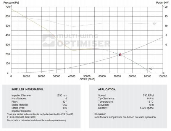
Recorded fan parameters for the Turkmenistan cooling tower replacement.
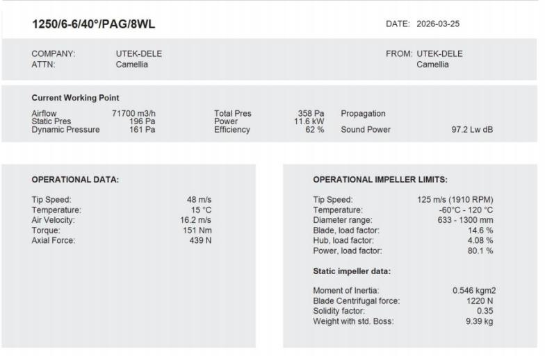
Measured values used to specify the replacement: diameter, blade count, speed and motor data.
The values in these sheets are project-specific: U10W blades are built to the diameter, blade count and angle the tower requires, so the useful reading is the method rather than a universal number. Compare the two columns, note which values are fixed by the existing ring and shaft, and treat the rest as the variables that the replacement can improve.
Note on the data: the figures in these sheets are reproduced from the project documents for reference only. Actual performance depends on the tower, the fill condition and the drive, so a replacement set is always quoted against measured site data rather than against a catalogue value.
The U10W Answer: Geometry, Material and Hub
The U10W is a large-diameter adjustable-pitch axial fan blade developed for slow-turning, high-airflow duties such as cooling towers, engine cooling and industrial ventilation. It is built in the 1000–2200 mm class with 6, 7, 8 or 10 blades on the W-3 hub family, in PAG or conductive PAGAS, and it is supplied as a balanced set.
Three changes separate it from the thin-blade generation it replaces.
1. A thicker, wider and longer blade section
The section is widened chord-wise and thickened at the root, with the material increasing toward the hub rather than remaining uniform along the span. That is the correct way to carry a cantilever bending moment: the root, which carries the full load, gets the most material. The result is a stiffer blade that holds its angle under load, which in turn keeps the airflow stable over the operating range instead of drifting as the blade deflects.
2. A hub interface designed for the load path
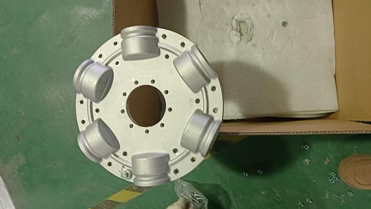
The blade root is carried in the W-3 hub with a generous seating area and a controlled radius at the transition, so the load spreads into the hub over a larger surface instead of concentrating at one fillet. Blades are set at the angle required by the duty and locked; the setting is recorded so that a future replacement set can be built identically.
3. Balanced as a complete impeller
Every U10W set is assembled on its hub and dynamically balanced on a hand laser balancing machine before shipment. Balancing the assembly rather than the individual blades is what makes the result meaningful: the balance condition that matters in service is the one the tower will see, with all blades and the hub together.
Because the blades are adjustable, the same hardware can be re-set if the tower duty later changes — for example if a fill pack is replaced with a different pressure drop, or if the fan speed is altered. That flexibility is retained without changing the structural design that fixed the failure mode.
About the U10W Design
The U10W was developed from the 8W and U8Z platforms. The blade is wider, thicker and longer than the earlier section, and the additional material is concentrated where the bending moment is highest — at the root — so the blade holds its angle under load instead of flexing as the fan runs.
Key advantages
High structural integrity. Unlike the structurally ”soft“ and failure-prone 8W design, the U10W carries the root load through a thicker section and a generous hub interface, which is the change that removes the fatigue cracking seen on the failed sets.
Stable airflow over the duty range. A stiffer blade keeps its effective angle, so airflow does not drift as the fan is loaded.
Balanced as a complete impeller. Blades and hub are balanced together, giving the plant a documented baseline to trend against.
Adjustable pitch retained. If the tower duty changes — a new fill pack, a different drive ratio — the blade angle can be re-set and recorded rather than the hardware being replaced.
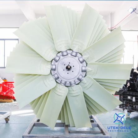
U10W blade set: widened, thickened and lengthened section compared with the earlier 8W platform.
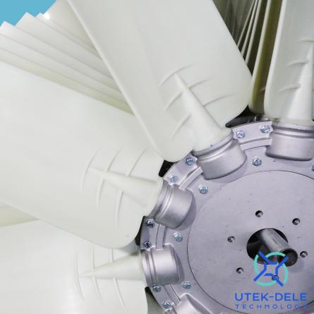
U10W hub and blade root detail — the load path that replaced the failure-prone interface.
Because the blades are adjustable, the same hardware can be re-set if the tower duty later changes, without changing the structural design that fixed the failure mode.
Materials and Temperature Limits
Blade material decides how a fan behaves as the duty moves toward its limits. UTEK-DELE supplies three materials across the range, and the choice for a cooling tower is normally made on temperature, chemical exposure and the consequence of static discharge.
| Material | Composition | Working temperature | Typical duty |
|---|---|---|---|
| PAG | PA6 + 30% glass fibre | -40 °C to 110 °C | General heavy-load cooling, cooling towers, ventilation |
| PAGAS | PA6 + 15% carbon + 15% glass fibre, conductive | -30 °C to 100 °C | Duties where static discharge must be avoided |
| Aluminium ADC12 | Die-cast aluminium alloy | Up to 150 °C, short-term 300 °C for 2 hours | High-temperature duties, engine and process cooling |
For most cooling tower installations the PAG blade is the correct starting point: the plume temperature stays well inside the material's range, and the glass-fibre reinforcement gives the stiffness that keeps blade angle stable. PAGAS is selected where the process or the electrical environment makes static discharge a genuine concern — conductive blades bleed charge away instead of allowing it to accumulate. Aluminium is reserved for duties where radiant heat or process temperature would take a polymer blade outside its working range.
Material documentation travels with the order. For this project the record included UV resistance testing for the polymer blade, fire-behaviour evidence for the PAG compound, and the material certificate of analysis for the batch used in the blades — the same documents that the certification block further down this page refers to.
Balancing, Inspection and Quality Records
A fan blade set is only as good as the inspection that follows it. The workflow used for this order, and for U10W sets generally, runs through five checkpoints before a set is released for shipment.
Moulding and dimensional check — blade length, chord, thickness at defined stations and root seating dimensions are measured against the drawing.
Root and hub fit — each blade is fitted to the hub pocket and checked for seating contact and correct locking; the blade angle required by the duty is set here.
Assembly into a complete impeller — blades, hub and fastener set are assembled as the tower will see them, not as loose components.
Dynamic balancing on a hand laser balancing machine — the assembled impeller is spun and corrected until residual unbalance is inside the acceptance limit; the reading is recorded against the set.
Final visual and marking check — blade count, angle marking, set identification and packing protection are confirmed; where transport would disturb the setting, the set is marked for disassembly and re-torque on site.
Two details from this project are worth highlighting because they matter on every tower installation. The first is that one test set was deliberately marked for disassembly after balancing, so that transport to Turkmenistan could not shift the blade angles. The second is that the official order was shipped with the same inspection records as the test set, so that the balancer's numbers could be compared with the site vibration reading taken after installation.
Why the record matters: When a tower fan is commissioned, vibration is measured. Without a factory balance record, nobody knows whether a reading of 4 mm/s means "as balanced" or "degraded". With the record, the same number becomes a baseline that can be trended over the following years.
The certificate block below shows the documents that support this kind of order: granted patents covering the blade and reversible fan designs, ISO9001 quality management and ISO14001 environmental management certification, and material test reports. If your project requires a specific document in a specific format, it can be prepared with the quotation rather than after the order.
Certifications & Quality Assurance
We are certified to ISO 9001:2015 Quality Management System, ISO 14001:2015 Environmental Management System, ISO 9001:2015 (UTEK Composite), Chinese Utility Model Patent — Explosion-proof Fan Blade, Chinese Invention Patent — Variable-pitch Reversible Fan, Chinese Utility Model Patent — Adjustable Blade-angle Fan System and more.
Shipment, Installation and Commissioning
Large fan blades are awkward cargo: they are long, comparatively light, and easy to damage at the tip and the root. Packing for this order therefore treated the blade set as an assembly rather than as a stack of parts, with blades protected along their span and the hub face protected separately.
On site, the sequence that avoids surprises is short but worth following exactly:
Measure before you dismantle. Record the fan ring diameter, shaft diameter, keyway and the vertical position of the impeller relative to the fan stack while the old fan is still assembled. These numbers decide whether the new hub seats correctly.
Check the shaft and bearings. Blade failure often coexists with worn bearings or a scored shaft. Replacing blades on a damaged shaft transfers the problem to new hardware.
Inspect the fan stack and supports. Any local repair on the tower structure must be complete before the new fan is fitted, because a distorted stack changes the tip clearance and therefore the vibration behaviour.
Assemble to the recorded angle. Each blade carries a setting mark. Re-torque fasteners in a cross pattern to the specified value; do not rely on "tight enough".
Confirm tip clearance and rotation direction. Clearance must be even around the full circumference, and rotation must match the airflow direction of the tower before the fan is run at speed.
Run up and record. Start at low speed where a variable-speed drive is fitted, note vibration and current at the operating point, and compare the vibration reading with the factory balance record.
Commissioning is also the moment to write down the settings. Blade angle, speed, current, vibration and any unusual noise become the reference for every later inspection. Towers that are commissioned with a written record are far easier to diagnose two years later, when the only question that matters is whether something has changed.
Maintenance and Spare Parts Strategy
Blade service life in a cooling tower is decided as much by inspection habits as by design. A practical schedule for the U10W class is:
Monthly (visual, from the tower deck): look for deposits on blades, water carry-over, uneven deposit patterns, and any change in the plume that suggests reduced airflow.
Quarterly (vibration trend): record vibration at a fixed operating point. The absolute value is less important than the trend; a rise over 2–3 readings indicates deposits, a loose fastener or a changing blade angle.
Annually (torque and inspection): check hub fasteners and blade-root seating, look for cracking at the root transition, and clean deposits with a soft method that does not scratch the surface.
After any tower structural work: re-check tip clearance and re-run the vibration reading, because the airflow field around the fan has changed.
Spares should be planned around the outage, not around the failure. Because the blades are adjustable and built to a recorded angle, a replacement blade can be supplied against the set record and fitted without re-setting the whole fan. Holding one spare blade per fan size, plus the specified fastener set, converts a potential multi-day outage into a scheduled two-hour job.
Where a plant runs several towers of the same size, standardising on one hub family simplifies this further: blade sets become interchangeable between fans, and the spare holding can be shared across the site instead of duplicated per tower.
Designing the Replacement: The Engineering Sequence
Replacing a failed fan properly is a specification exercise, not a parts lookup. The sequence below is the one used on this project and on cooling tower replacement orders generally; it is deliberately short, because each step produces a number that the next step depends on.
Step 1 — Record the installation as it stands
Before anything is dismantled, measure the fan ring internal diameter, the shaft diameter and keyway, the hub seating face, and the axial position of the impeller in the stack. Photograph the assembly with a tape measure in frame. These measurements decide whether the replacement hub will seat correctly and whether the blade tip can be held at a safe clearance. On older towers the ring is rarely perfectly round, so record the minimum clearance as well as the nominal diameter.
Step 2 — Establish the duty the fan must deliver
Duty comes from the tower, not from the failed blade. Useful inputs are the design airflow, the water flow and range the tower is expected to handle, the fan speed or the drive ratio, the motor power actually installed, and the temperature of the air leaving the fill. Where the original documentation has been lost, the motor nameplate plus measured water temperatures give a workable estimate of the duty point. A fan that is specified against a duty can be verified after installation; a fan specified against a part number cannot.
Step 3 — Choose blade section, count and angle
With diameter fixed by the ring and duty fixed by the tower, the blade count and angle are selected together to reach the airflow at an acceptable shaft power. Fewer, wider blades generally give a slightly higher pressure capability for the same diameter; more, narrower blades spread the load and reduce blade-passing noise. The angle is then set at the point that delivers the airflow without pushing the motor beyond its rating — and it is recorded, because the next set will be built to the same figure.
Step 4 — Confirm material and interface
Material follows temperature and environment, and the hub interface follows the shaft measurement from step one. This is also the moment to decide whether the fan should be supplied as a blade set only, as a complete balanced impeller, or as a full assembly with hub and fasteners. On a tower, a complete balanced impeller is normally the right answer: the balance condition is then the responsibility of the factory rather than the site crew.
Step 5 — Plan the outage around the delivery
Finally, align the delivery with the outage. Confirm that the blades will arrive assembled to the recorded angle and protected for transport, decide whether they will be re-torqued on site, and make sure the crane or hoist capacity for the tower deck is enough for the heaviest single item. Most delays in fan replacement are logistics rather than engineering.
Ordering tip: send photographs of the hub and shaft interface with the enquiry. A measured shaft drawing removes the most common source of delay between quotation and shipment.
Why Adjustable Pitch Matters in Cooling Tower Service
A fixed-angle blade is efficient only at the duty point it was moulded for. Towers, however, rarely stay at one duty point for their whole life. Fill packs are replaced with a different pressure drop, a motor is changed, a drive ratio is altered during a refurbishment, or the site decides to run the tower at reduced water flow during part of the year. Each of those changes moves the fan away from its design angle.
An adjustable-pitch blade such as the U10W absorbs that change. The blade remains the same casting; only the setting changes, and the setting is a documented value rather than a manufacturing decision. In practice this delivers three benefits.
Power correction without new hardware. If the motor is overloaded at the operating point, reducing the blade angle lowers shaft power immediately — a far cheaper correction than changing the motor or the drive.
Airflow correction when the tower underperforms. Where the measured approach temperature shows the tower is not reaching its design duty, a modest increase in blade angle restores airflow at the same speed, provided the motor has margin.
Interchangeability across a plant. Towers of the same size share a hub family, so a spare blade set can serve any of them, and the setting can be matched to each tower from its own record.
There is a discipline attached to that flexibility: every adjustment must be recorded. A fan whose angle has been changed twice without documentation is a fan whose performance can no longer be explained from its records. The UTEK-DELE practice of marking the angle on each blade and keeping it with the set identification is what keeps the option usable years later.
In this project the adjustable feature also solved a transport problem. A large blade set can be balanced as an assembly, then partly dismantled so that shipment cannot shift the setting, and re-assembled on site to the marked angle — the balance record and the angle record travel together, so the fan arrives at the tower with its performance defined rather than assumed.
Cost, Downtime and the Specifying Checklist
The economics of a fan replacement are dominated by the tower being out of service, not by the blades. A derated generating unit or a process line running hot because a cooling tower is down usually costs more per day than the fan set costs in total. That is the reason blade sets for critical towers are specified with factory balancing, documented inspection and protection for transport: it moves work out of the outage and into the factory, where it is cheaper and more controllable.
A simple checklist for anyone preparing a similar replacement:
Fan ring internal diameter — measured, with the minimum clearance noted on out-of-round towers.
Shaft diameter, keyway and hub seating — measured, with photographs.
Speed and motor rating — from nameplate plus drive ratio if the fan speed is not directly known.
Duty point — design airflow, or measured water flow and temperature range.
Environment — plume temperature, salt carry-over, chemical exposure, UV exposure on the upper deck.
Material decision — PAG, conductive PAGAS or aluminium ADC12, with the temperature margin stated.
Scope of supply — blades only, balanced impeller, or complete assembly with hub and fasteners.
Documentation — balancing record, dimensional records, material certificate, UV and fire test reports, and the angle record for the set.
Packing and transport — whether the set ships assembled or marked for re-assembly on site.
Commissioning record — the place where the numbers taken on site are written down next to the factory figures.
Work through that list before asking for a quotation and the enquiry answers most of the questions a manufacturer would otherwise have to ask. On this project the list was completed before the order was placed, which is why the replacement could be shipped against a recorded specification instead of being adapted on the tower deck.
If the failed fan is still available for inspection, its damage pattern is also worth recording: where the crack started, how it progressed, whether the failure was on one blade or several, and what the deposit pattern looked like. Those observations turn a replacement into a diagnosis, and they are the evidence that shows whether the new specification has actually addressed the failure mode.
The Fans Used in This Replacement
The blade sets fitted to this project are built on the same large-diameter platform shown below. Both are adjustable-pitch blades, balanced as complete impellers before shipment.
 U10W large axial fan |  9W axial fan blade |
Video: Fan Blade Manufacture and Pitch Control
11W Adjustable-Pitch Axial Fan Blade for High Performance — Field Installation | UTEK-DELE — watch on YouTube
Frequently Asked Questions
What caused the 8W fan failures in this project?
The failed blades were thin-section moulded blades operating continuously in a cooling tower. The section was slender for the bending load at that diameter, the blade-to-hub transition concentrated stress at a small radius, and deposit build-up produced imbalance that added an alternating load. Cracks initiated at the root region and progressed until material was released.
Which U10W configuration replaced the 8W fans?
The U10W platform is built in the 1000–2200 mm class with 6, 7, 8 or 10 blades on the W-3 hub, in PAG or conductive PAGAS. The exact diameter, blade count and blade angle for this project were set against the existing fan ring and are shown in the parameter comparison table on this page.
Can the U10W be fitted without modifying the tower?
In most cases yes. The replacement is engineered to the existing fan ring, shaft and keyway, and the hub is quoted against the measured shaft interface. Where the tower structure has been repaired locally, the stack should be checked for distortion before the new fan is fitted so that tip clearance stays even.
Is the fan balanced before shipment?
Yes. Every set is assembled on its hub and dynamically balanced on a hand laser balancing machine, and the balance record travels with the order. The site vibration reading taken at commissioning is then compared against that record rather than judged in isolation.
Which blade material should be chosen for a cooling tower?
PAG (PA6 + 30% glass fibre, -40 °C to 110 °C) is the normal choice for tower service. Conductive PAGAS (-30 °C to 100 °C) is used where static discharge must be avoided, and aluminium ADC12 (up to 150 °C, short-term 300 °C for two hours) is used where process temperature exceeds the polymer range.
How is blade angle set and recorded?
Blade angle is set at assembly to the duty point required by the tower and marked on each blade. The value is recorded with the set identification, so a later replacement blade can be produced and fitted to the same setting without re-engineering the fan.
What is the lead time and what documentation is supplied?
Lead time depends on blade count and material and is quoted per project. Documentation typically includes dimensional and balancing records, material certificate of analysis, UV resistance and fire-behaviour reports for polymer blades, and ISO9001 / ISO14001 certificates. Project-specific documents can be prepared with the quotation.
Can this upgrade be applied to other towers with thin-blade fans?
Yes, and it is usually worthwhile where the tower runs continuously, where carry-over deposits cannot be eliminated, or where blade failure would force a derate. The method is the same: measure the existing fan installation, confirm the duty, and specify the blade section, material and hub against that duty rather than against the failed part number.
Related Products and Further Reading
The U10W belongs to the large-diameter end of the UTEK-DELE blade range. The pages below cover the blade platform itself, the W Series family it sits in, and the application pages for the duties discussed in this case study.
6W large-diameter axial fan blade for engine and process cooling
Cooling tower fan applications — duty, failure modes and replacement practice
Industrial axial fan impellers — balanced blade and hub assemblies
Summary
This project replaced a generation of thin-section fans that had cracked in service with U10W blade sets engineered for the same duty: a thicker, wider section that carries the root bending load, a hub interface that spreads that load instead of concentrating it, and a documented balancing step that gives the plant a baseline to trend. The fans were inspected, marked, packed and shipped against a recorded specification, and the installation was planned so the tower outage stayed inside its window.
If your tower is running fans of the same generation and you want to know what a U10W replacement would involve for your ring diameter, blade count and duty, send the fan data — existing diameter, blade count, speed, motor power and the airflow or temperature rise the tower must deliver — and we will quote the set against those numbers.


